Part 2: Printer Sections
This is the second installment in a series by Jim Brown, a corrugated equipment specialist with more than three decades of experience. Articles will outline what the board experiences during the conversion process, but from an unusual perspective: that of the board itself, in the form of our imaginary narrator, Corra Gator-Boardy.
Ride along with Corra in a series of six mini-adventures on her way from a flat corrugated board to an amazing, corrugated container. Learn about the mechanisms and devices that will launch her into the machine, color her panels, cut out her unique shapes, form her dimensions, hold her together, and prepare her for market.
In our last adventure, Corra had been loaded and launched out of the feed section of the machine, was up to proper board speed, and headed into the first print section. She looked up to see a series of roller wheels, this time positioned above her. These were made of smooth, hard-anodized aluminum. As she advanced into the first print section of the machine, a vacuum blower pulled her tightly against the wheels that protruded through stainless steel grate openings above her. She was traveling at the exact same speed as the surface of the feed rolls.
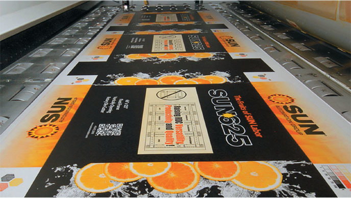
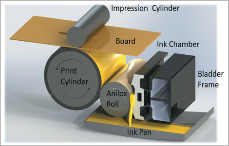
Just ahead was a second nip, the impression nip. This was the gap between the smooth, chrome-plated, nine-inch diameter impression roll above and the print cylinder below. The print cylinder was wrapped with a custom, soft, urethane print plate that had an image of slices of fruit and some wording engraved into it. The image was coated with a film of yellow, water-based ink. As she rolled forward, the image was transferred onto her outer liner at exactly the right speed. The impression roll helped to ensure that the image was impressed the perfect amount onto her outer liner. Unlike the other nips, this nip is adjustable by raising or lowering the entire upper blower/roller assembly that also contains the impression roll. Just like the feed roll nip, the impression nip pressure must be very precisely adjusted. If it is too far open, the print will skip. If it is adjusted too tightly, the print will create a smudged image.
Corra was really excited now. She had some yellow color and was heading for red! It was a peaceful transition from print unit one into print unit two. She had time to reflect on how the ink had been pumped from the ink bucket to the single blade ink chamber, where it had filled the cells of the anilox roll. The surface of the anilox roll has tiny, reverse pyramidal-shaped cells that are laser engraved into the ceramic-coated surface. There were 250 cells in one linear inch of roll, with the volume of ink that each cell could hold measured in billion cubic microns. Next, the excess ink was “doctored” off the anilox roll surface by the doctor blade to create an ink film of precise thickness that would transfer onto the print cylinder plate.
The doctor blade is the width of the anilox roll and made of plastic, with a bevel on it, much like a disposable putty knife. The main ink flow, along with the ink scraped off the anilox roll, runs out of the ends of the ink chamber into the ink pan and is pumped back to the ink bucket. The ink pump works like a human heart, with check valves that open and close as the pump cycles—first drawing in ink, closing, and then pushing it out.
Now she was ready to receive red ink from a print plate that was slightly different, but complementary to the yellow one. And in a flash, half of the fruit image turned orange as the red printed over the yellow. With just enough time to let her ink soak in and dry, she raced through print two and headlong into print three. She was a pro now and was prepared to receive a nice heavy coat of black ink, which made her new image pop. But how, Corra wondered, are my colors aligned?
She remembered learning about a print registration datum target. This is a bullseye symbol located in the same spot on all the various color print plates. It demonstrates if the various print unit plates are positioned correctly in relation to one another. There is usually some small amount of acceptable error left and right (lateral registration) and up and down (rotational registration).

To adjust the lateral registration, a print cylinder and its plate must be moved left or right using the lateral adjust mechanism. It is commonly a manual apparatus with a threaded adjust shaft and an aluminum handwheel. When you turn it counter-clockwise, the print will move slightly to the operator side of the machine (where the operator stands). Conversely, a clockwise turn of the handwheel will move it to the drive side of the machine (where the drive motor is located).
Changes in rotational registration require the print cylinder and plate to be advanced clockwise or retarded counter-clockwise. This is accomplished through the print register, which is a motorized differential device. Some are sophisticated, servo motor-driven, harmonic drive units, whereas the older ones are worm gear, electric motor-driven devices. Both lateral and rotational registration can be done with or without the machine running. When the first sheet is run, an operator can measure the amount a color is off and make the necessary adjustment, until all colors are printing as close to on top of one another as possible. The datum target shown in this article is a sample of cyan, magenta, yellow, and black showing their positions, relative to one another. This will affect the accuracy of the images on the sheet, a visible measure of quality.
Next, things will be getting much more intense, as our corrugated sheet will soon fly into the sharp teeth of the die cutter section.
has more than 30 years of experience in engineering and machine design for the corrugated industry. He is currently the Manager of Purchasing at Sun Automation Group.
 The Conversion of Corra Gator-Boardy